TLDR; A little bit, yes, but it probably doesn't matter.
The new Raspberry Pi Pico 2 mostly represents a bump in performance and memory.
A welcome feature of the release, for authors such as myself, is that the functioning of the GPIO pins and the pinout remains the same as the original Pico 1, as does the most used microPython programming environment,
So, it was a surprise to find various reports of a hardware bug affecting GPIO pins. My main concern was, does this affect the way GPIO pins are used in the examples for my book Programming the Pico, as well as the instructions for our Pico electronics kit.?
The Problem
You can find the formal explanation of the bug in the
RP2350's datasheet - on page 1341 (yup, perhaps don't start looking for it on page 1). The detail is somewhat complex, affecting only the situation where a GPIO pin (any) is used as a digital input with the internal pull-down resistor enabled.
Digital Input (Internal Pull-UP resistor enabled)
Before we look at the problem scenario, let's try out the more common situation where a GPIO pin is sued as a digital input with the internal PULL_UP resistor enabled.
Here is the example code (from Programming Pico).
from machine import Pin
from utime import sleep
switch = Pin(10, Pin.IN, Pin.PULL_UP)
while True:
print(switch.value())
sleep(0.1)
In this scenario, the internal pullup resistor is enabled by the line of code:
switch = Pin(10, Pin.IN, Pin.PULL_UP)
.. this keeps the GPIO pin (10 in this example pulled up to the 3.3V supply voltage, registering as a 1 when it's value is read. This resistor, that is built into the PGIO hardware of the RP2350, has a value of a few 10s of kΩ. When the switch is pressed, this relatively weak pull-up is overpowered as the switch connect the GPIO pin to GND (0V). The input then registers as a value of 0 when read.
When you run the program, you will see something like this.
By default, the value shown in the Shell area is 1, but when the switch is pressed, it changes to 0. Here's the breadboard layout using parts from the MonkMakes
Electronics Kit 1 for Pico.
So, in short, this works just fine. No problem here.
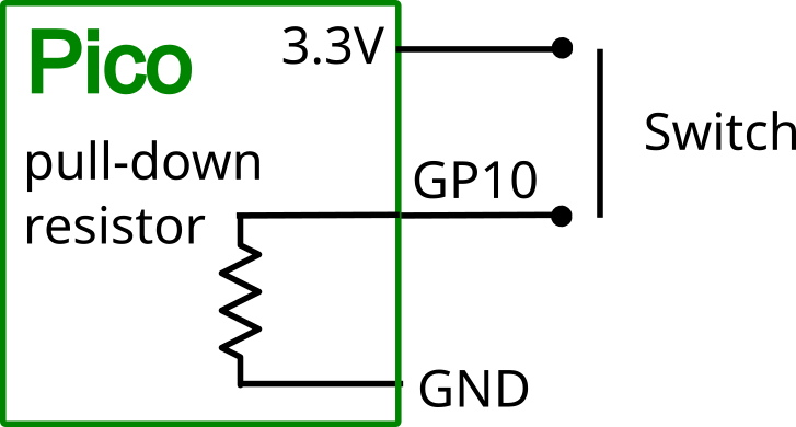
Digital Input (Internal Pull-DOWN resistor enabled)
Some microcontrollers do not even have the option of a built-in 'pull-down' as opposed to 'pull-up' resistor. Generally switches on digital inputs connect the GPIO pin to GND (0V) when pressed. This is the safest option, as generally boards only have one GND of 0V, but may have several supply voltages (3.3V and 5V -- in the case of a Pico). Connecting 5V to a 3.3V digital input can destroy that input on may GPIO designs, so it's much safer to use pull-up resistors and cope with the inverted logic of 0 meaning pressed and 1 meaning not pressed in your code.
Having said that, the feature is there, so people will make use of it. So, here is the problem situation, of digital inputs with a built-in pull-down resistor.
This is shown on breadboard, here, where the switch is now between GPIO 10 and 3.3V on the Pico. There are also 2 more leads connected to a DMM acting as a voltmeter measuring the voltage at GPIO 10.
Here is the code. All that's changed is that Pin.PULL_UP has become Pin.PULL_DOWN
from machine import Pin
from utime import sleep
switch = Pin(10, Pin.IN, Pin.PULL_DOWN)
while True:
print(switch.value())
sleep(0.1)
When I run the program, there is immediately a problem apparent. The Shell is reporting values at the GPIO pin of 1. This should be 0, because the switch is NOT pressed and the pull-down resistor is enabled. The voltmeter is reading 2.11V, which is above the threshold for being a high input (reading a value of 1).
If I then press the button, there is no change to the output in the Shell, it is still saying 1, but the voltage at the PGIO pin is now 3.3V as you would expect.
So, if the GPIO acting as an input, actually suddenly looks like an output at 2.11V, how much current flows through the GPIO pin when we press the switch connecting it to 3.3V?!
Connecting the multimeter to the GPIO pin to measure the current drawn, then the answer is a reassuringly tiny current of just 60µA. So, we are not going to burn anything out.
So, in short, don't try and use the built-in pull-down resistors, they don't work.
Conclusion
The internal pull-up resistor feature of digital inputs works just fine, but the pull-down feature does not work. I can live with that, because it's better practice to just use pull-up resistors.
So, should you buy a Pico 2? Yes, unless you really ned to use internal pull-down resistors.
Note that my Pico 2, was bought in September 2024, so you might find that this has been fixed in the silicon that you have.