Its a small project-based book, that gets you started using IOIO boards.
IOIO boards are interface boards that allow you to connect electronics to your Android phone or tablet.
Although IOIO will work with Google's Open ACcessory standard, it will also work with the much older ADB standard which means that almost any Android phone will work with IOIO.
IOIO will work with either a USB cable or using a low cost Bluetooth USB dongle, making it great for robotic control applications.
Projects
Here are the projects that you can build using the detailed step-by-step instructions in the book. Each project description includes a parts list.
PIR movement detector - sends an SMS when movement detected.
Temperature logger - to SD on the phone, Bluetooth or USB
LED Matrix - 8x8 multicolor LED Matrix, with animations
Bluetooth rover
All the source code for the projects is provided on the book's website.
About the Author These are my books. Click on the image below to find out more about them.
I saw a great presentation by Philip Lindsay on a technology that he had developed called 'Handbag' at the Android Open conference last month.
Handbag is another way to write the code part of an Android Accessory. That is to link an Android phone that supports Open Accessory to an Arduino. The Arduino part might be an Arduino Uno with a USB Host shield, or a specialist board such as the Freetronics USBDroid board that I reviewed a few weeks ago (http://srmonk.blogspot.com/2011/10/freetronics-usb-droid-review.html).
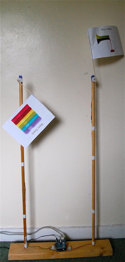
I decided to try out Handbag to control a couple of servos that raise little paper flags in a project I developed for my book 'Arduino + Android Projects for the Evil Genius'. In the book, the servos were attached to an Arduino / Ethernet shield combination. In this case, I decided to attach them to a USBDroid board, although an Uno and USB host shield would work just as well.
Philip's stroke of genius was to realise that if the Arduino is acting as the host in the USB relationship (as it does) then it might as well be in charge of telling the Android phone what to do. In other words, there is zero programming to be done on the Android side, instead you put code in your Arduino script that tells a general purpose Android app what to display in its UI and to do when someone presses a button etc.
I'll just say that again! Genius!
Step 1. Downloading the Handbag App onto my Android Phone.
So, my first task was to fetch the general purpose Handbag app down for my Android phone.
Its not on the Android Market, so I downloaded the APK binary from here. For your convenience here is a QR code for it.
Note that because this App is not from the Market, you have to allow your phone to download apps from 'Unknown Sources'. You will find this in Settings->Applications.
When the App starts, it should look like this.. Philip, I stole that image from your web site - hope thats okay.
Step 2. Setup the Arduino Environment
If you haven't used the Android ADK, then you will need to install the necessary libraries onto your Arduino IDE. To do this, you just unzip the library files here into your libraries folder which will be in the Arduino folder in your documents folder, so on a Mac thats in ~/Documents/Arduino. If there isn't a 'libraries' folder there, make one.
Then unzip this file and copy its 'Handbag' folder into the libraries folder.
You will also need to install the ADK library and a modified USB host library. These live in these two locations.
Note that if you are using a Uno and USB host shield or a USB Droid board then, when installing the ADK (first link) don't install the USB Host library that comes with the ADK download, use the one that come in the second link instead.
Step 3. Upload this minimal sketch to your Uno or USBDroid.
You will also need to attach an LED and resistor to pin 4, as shown below.
Initially I tried to use 13 as the LED pin to make use of the built-in LED, but that seems to be reserved for use somewhere, so I had to resort to using an LED on pin 4.
Lets just pause for a moment. We have 37 lines of code here. If you want to see the equivalent is writing it long hand in Android, you could add at least one zero to the lines of code.
Have a quick read through the code above. Its really very easy to see how to use Handbag.
So, lets change my flags code to use Handbag.
Here is the wiring diagram, it shows an Ethernet Board, but its the same pin numbers as an Uno or USB Droid.
And here is the sketch:
#include <Servo.h>
#include <Max3421e.h>
#include <Usb.h>
#include <AndroidAccessory.h>
#include "Handbag.h"
#define REQUEST_BUFFER_SIZE 700
#define MIN_ANGLE 30
#define MAX_ANGLE 175
// pins 10, 11, 12 and 13 used by Ethernet
#define SERVO_1_PIN 2
#define SERVO_2_PIN 3
Servo servo1;
Servo servo2;
int servo1pos = MIN_ANGLE;
int servo2pos = MIN_ANGLE;
AndroidAccessory acc("rancidbacon.com",
"Handbag",
"Handbag (Arduino Board)",
"0.1",
"http://rancidbacon.com",
"0000000000000001");
HandbagApp Handbag(acc);
void setupHandbagUI()
{
Handbag.addLabel("Evil Genius Flags");
Handbag.addButton("Raise Flag 1", raiseFlag1);
Handbag.addButton("Lower Flag 1", lowerFlag1);
Handbag.addButton("Raise Flag 2", raiseFlag2);
Handbag.addButton("Lower Flag 2", lowerFlag2);
}
void setup()
{
Handbag.begin(setupHandbagUI);
servo1.attach(SERVO_1_PIN);
servo2.attach(SERVO_2_PIN);
}
void loop()
{
Handbag.refresh();
servo1.write(servo1pos);
servo2.write(servo2pos);
delay(100);
}
void raiseFlag1()
{
servo1pos = MAX_ANGLE;
}
void lowerFlag1()
{
servo1pos = MIN_ANGLE;
}
void raiseFlag2()
{
servo2pos = MAX_ANGLE;
}
void lowerFlag2()
{
servo2pos = MIN_ANGLE;
}
And here is a short video of the flags in action. It all worked like a dream.
In short, Handbag is a wonderfully simple way to make Android accessories without having to learn large amounts about Java programming and the Android libraries.
About the Author These are my books. Click on the image below to find out more about them.
5 Stars! The best thing to come out of Australia since Rolf Harris!
I was given one of these boards at Android Open, and rather like the IOIO of my previous Blog, I have only just got around to having a play with it.
It is intended as an alternative to the Android ADK reference board which is Arduino Mega-based and so probably overkill for most Android Accessories that you are likely to make. The USB Droid is far more practical in size.
It comes in a nice retail pack, with a Mini USB lead which is used to connect it to your computer rather than the 'normal' Arduino USB-B connector - good choice.
And that is where the magic starts...
The board is extremely well made, and well thought out. When I plugged the Mini USB into my computer I was surprised to see a green LED light along with the blue power LED.
The green LED is labelled VBUS and yes, the USB 5V is passed through from your computer and out of the USB-A connector to your phone. A really nice touch as you don't have to use an external power supply while you are developing.
I am not sure Putting a Micro SD card on there is much use for making Android accessories, as effectively all the storage of the phone is available to you. But I guess you could make a data logger that worked off-line until you connected it to the Android phone to send the data to Pachube. Also it could come in handy for other types of USB host projects.
I have a minimal Android Open Accessory test app that I describe in my Arduino + Android book. You can download it from here (the app that is, not the book). There are also slides from my talk at Android Open here that describe the app. All it does is send a number to the Arduino that increments it and sends it back.
The sketch installed and ran perfectly.
I am very impressed with this board, its certainly a lot neater than an Uno with a USB host shield on the top.
I see that Freetronics have done similar things with an Ethernet board. I look forward to trying out one of these.
About the Author These are my books. Click on the image below to find out more about them.
I picked up a IOIO (apparently pronounced YoYo) from Android Open and I have just had chance to play with it.
Unlike the Arduino, IOIO is not intended to operate independently. It has to be paired with an Android phone. While it can use the Android Open Accessory protocol, it can also use plain old ADB which means that it works on most phones rather than the smaller choice of phones that Open Accessory works on.
I even tried an old Android 1.6 LG phone that one of my kids cast off six months ago and it works just fine.
When creating a project, you do not change the firmware on the IOIO, but rather you issue commands that read values from pins and turn pins on and off from the Android app.
It took 10 minutes to get the example working that turns the on-board LED on and off from a little Android app. Although I had Eclipse and the Android SDK already installed. These are probably the most complex part of setting up.
IOIO sets out to do just one job and do it well. It is not a general purpose board like the Arduino, and for $50, it is just cheaper than an Arduino and USB host shield and smaller and neater.
I like it a lot and it looks great. Far more IO ports than you are ever likely to use. In fact, I will probably solder 0.2 inch screw terminals onto the connectors and just use make every other IO available.
Pros.
Pot to adjust charging current to phone
Nice looking board
Good documentation set on the Wiki (https://github.com/ytai/ioio/wiki)
Cons.
Only 20mA output current per IO pin (Arduino can do 40mA)
3.3V logic, but some pulls can cope with being pulled up to 5V
No Power socket, you have to solder power leads on. This means that to do anything with the board, you will need to solder.
Edit: I forgot to mention that IOIOs with the latest firmware can accept a cheap Bluetooth dongle and work seamlessly over BT. Even switching connection without restart if you plug in with USB.
About the Author These are my books. Click on the image below to find out more about them.
My new book 'Arduino + Android Projects for the Evil Genius' is now available for pre-order from Amazon. See the link to Amazon in the right-hand panel (scroll down a bit).
The cover on Amazon hasn't been updated yet, so it looks a little different.
The first books should be shipped around the start of December.
The projects are:
Chapter
Project
Notes
1
Bluetooth Robot
Control a small rover from your Android Phone using Bluetooth and an Arduino and Motor shield.
2
Android Geiger Counter
An Android Open Accessory Project using a USB host shield and Arduino Uno.
3
Android Light Show
A powered Open Accessory dock for your Android phone that drives three LED panels to make a sound sensitive light show.
4
Android TV Remote
Programmable Infrared remote control accessory for your Android phone.
5
Temperature Logger
A temperature logger that uses the Android phone to wirelessly send readings to Pachube.
6
Ultrasonic Range Finder
An Android Open Accessory for measuring distance.
7
Home Automation Controller
The Android tablet base unit with a audio jack interface to Arduino.
8
Home Automation Power Control
Add control of AC outlets and lights to the Home Automation Controller from Chapter 7.
9
Home Automation Thermostat
Add control of domestic heating to the Home Automation Controller using low cost RF data modules.
10
Remote Door Lock
Control access to your home using RFID tags, also with a RF link to the Home Automation Controller
11
Ethernet Flag
Network control of two flags that can be activated from any Internet device. Useful for the Evil Genius to summon minions.
12
Delay Timer
A simple to make Arduino-based delay timer.
About the Author These are my books. Click on the image below to find out more about them.
I have been spending some time recently working on Android Open Accessory using an Uno and the Sparkfun USB host shield. I'm including a range of accessories, Geiger counter, ultrasonic distance meter etc. in my soon to be released (well Dec 2011) book Arduino + Android Projects for the Evil genius
Although the feature that the accessory should provide half an amp at 5V to charge the phone is all very well for AC outlet powered accessories, it means battery powered accessories need a big battery.
Or does it?
I decided to do a bit of experimenting with a surplus USB extension lead that came with a USB modem dongle and just extends the USB lead a couple of inches.
Firstly simply cutting the red 5V USB power lead. This stopped the accessory being recognised and the charge indicator on my Nexus One did not indicate any charging (no surprise there).
If, however, I put a 1k resistor in line on the red 5V wire, everything works fine as an accessory, but the phone does not draw anything significant from the accessories battery, allowing it to be powered from a small 9V battery. At least it does if the phone is well charged.
WARNING: This result was derived experimentally. This may well void your phone warranty, if you connect it up like this. It didn't hurt my phone, but do it at your own risk. Also your wire may not use the same color coding as mine did, so red might be the wrong lead for you.
The following sequence of photos shows the construction of the lead.
Carefully cut away some of the outer plastic with a sharp knife on one side and tease out the shielded bundle of wires.
Scrape a gap between the shielding to get at the +5V wire.
Cut the red wire and strip and tin the ends.
Solder the 1k resistor into place. Then wrap it all up with insulating tape. Wrap the part behind the tape carefully, so that there is no chance of the bare leads from either side of the resistor making contact with the shielding wires or foil.
About the Author These are my books. Click on the image below to find out more about them.